		Combiner Commands And Explination
		==================================

	Any Link Below is truncated to the root of SDK Manual,
             NINTENDO%2064%20SDK%205_CDROM/man/allman50
		Can Also be downloaded at romhacking

		Compiled By Trevor
Credits to Zoinkity for Original Find |
| FC G_SETCOMBINE | ||
|---|---|---|
| typedef struct { | ||
| int | cmd:8; | |
| unsigned int | muxs0:24; cc1 ac1 | |
| unsigned int | muxs1:32; cc2 ac2 | |
| } Gsetcombine; | ||
| upper word | Value | Length (bits) |
Options applicable |
| 00F00000 | a0 | 4 | Combine, Texel0, Texel1, Primitive, Shade, Environment, Noise, 1, 0 |
| 000F8000 | c0 | 5 | Combine, Texel0, Texel1, Primitive, Shade, Environment , Scale, Combined_Alpha, Texel0_Alpha, Texel1_Alpha, Primitive_A, Shade_Alpha, Env_Alpha, LOD_FRACTION, Prim_LOD_Frac, K5, 0 |
| 00007000 | AA0 | 3 | Combine, Texel0, Texel1, Primitive, Shade, Environment, 1, 0 |
| 00000E00 | AC0 | 3 | Texel0, Texel1, Primitive, Shade, Environment, LOD_FFRACTION, Prim_LOD_Frac, 0 |
| 000001E0 | a1 | 4 | Combine, Texel0, Texel1, Primitive, Shade, Environment, Noise, 1, 0 |
| 0000001F | c1 | 5 | Combine, Texel0, Texel1, Primitive, Shade, Environment, Scale, Combined_Alpha, Texel0_Alpha, Texel1_Alpha, Primitive_A, Shade_Alpha, Env_Alpha, LOD_FFRACTION, Prim_LOD_Frac, K5, 0 |
| lower word | |||
| F0000000 | b0 | 4 | Combine, Texel0, Texel1, Primitive, Shade, Environment, center, k4, 0 |
| 0F000000 | b1 | 4 | Combine, Texel0, Texel1, Primitive, Shade, Environment, center, k4, 0 |
| 00E00000 | AA1 | 3 | Combine, Texel0, Texel1, Primitive, Shade, Environment, 1, 0 |
| 001C0000 | AC1 | 3 | Texel0, Texel1, Primitive, Shade, Environment, LOD_FFRACTION, Prim_LOD_Frac, 0 |
| 00038000 | d0 | 3 | Combine, Texel0, Texel1, Primitive, Shade, Environment, 1, 0 |
| 00007000 | AB0 | 3 | Combine, Texel0, Texel1, Primitive, Shade, Environment, 1, 0 |
| 00000E00 | AD0 | 3 | Combine, Texel0, Texel1, Primitive, Shade, Environment, 1, 0 |
| 000001C0 | d1 | 3 | Combine, Texel0, Texel1, Primitive, Shade, Environment, 1, 0 |
| 00000038 | AB1 | 3 | Combine, Texel0, Texel1, Primitive, Shade, Environment, 1, 0 |
| 00000007 | AD1 | 3 | Combine, Texel0, Texel1, Primitive, Shade, Environment, 1, 0 |
| |||||||||||||||||||||||||||||||||||||||||||||||||||||||||||||||||||||||||||||||||||||||||||||||||||||||||||||||||||||||||||||||||||||||||||||||||||||||||||||||||||||||||
| |||||||||||||||||||||||||||||||||||||||||||||||||||||||||||||||||||||||||||||||||||||||||||||||||||||||||||||||||||||||||||||||||||||||||||||||||||||||||||||||||||||||||
The Equation looks like this
|
If we plug Runway (FC 26 A0 04 1F FC 93 FC) into it we get
|
| Preset names | ||||||||
| G_CC_ | (a - | b) * | c + | d | (A - | B) * | C + | D |
| PRIMITIVE | 0 | 0 | 0 | prim. | 0 | 0 | 0 | prim. |
| SHADE | 0 | 0 | 0 | shade | 0 | 0 | 0 | shade |
| SHADEDECALA | 0 | 0 | 0 | shade | 0 | 0 | 0 | texel0 |
| DECALRGB | 0 | 0 | 0 | texel0 | 0 | 0 | 0 | shade |
| DECALRGBA | 0 | 0 | 0 | texel0 | 0 | 0 | 0 | texel0 |
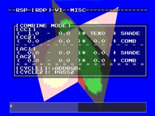
| ADDRGB | 1 | 0 | texel0 | shade | 0 | 0 | 0 | shade |
| ADDRGBDECALA | 1 | 0 | texel0 | shade | 0 | 0 | 0 | texel0 |
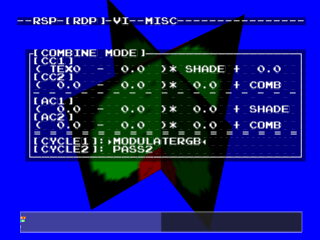
| MODULATERGB | texel0 | 0 | shade | 0 | 0 | 0 | 0 | shade |
| MODULATEI | texel0 | 0 | shade | 0 | 0 | 0 | 0 | shade |
| MODULATERGBA | texel0 | 0 | shade | 0 | texel0 | 0 | shade | 0 |
| MODULATEIA | texel0 | 0 | shade | 0 | texel0 | 0 | shade | 0 |
| MODULATERGBDECALA | texel0 | 0 | shade | 0 | 0 | 0 | 0 | texel0 |
| MODULATEIDECALA | texel0 | 0 | shade | 0 | 0 | 0 | 0 | texel0 |
| MODULATERGB_PRIM | texel0 | 0 | prim. | 0 | 0 | 0 | 0 | prim. |
| MODULATEI_PRIM | texel0 | 0 | prim. | 0 | 0 | 0 | 0 | prim. |
| MODULATERGBA_PRIM | texel0 | 0 | prim. | 0 | texel0 | 0 | prim. | 0 |
| MODULATEIA_PRIM | texel0 | 0 | prim. | 0 | texel0 | 0 | prim. | 0 |
| MODULATERGBDECALA_PRIM | texel0 | 0 | prim. | 0 | 0 | 0 | 0 | texel0 |
| MODULATEIDECALA_PRIM | texel0 | 0 | prim. | 0 | 0 | 0 | 0 | texel0 |
| REFLECTRGB | env. | 0 | texel0 | shade | 0 | 0 | 0 | shade |
| REFLECTRGBDECALA | env. | 0 | texel0 | shade | 0 | 0 | 0 | texel0 |
| BLENDI | env. | shade | texel0 | shade | 0 | 0 | 0 | shade |
| BLENDIA | env. | shade | texel0 | shade | texel0 | 0 | shade | 0 |
| BLENDIDECALA | env. | shade | texel0 | shade | 0 | 0 | 0 | texel0 |
| BLENDRGBA | texel0 | shade | texel0A | shade | 0 | 0 | 0 | shade |
| BLENDRGBDECALA | texel0 | shade | texel0A | shade | 0 | 0 | 0 | texel0 |
| BLENDPE | prim. | env. | texel0 | env. | texel0 | 0 | shade | 0 |
| BLENDPEDECALA | prim. | env. | texel0 | env. | 0 | 0 | 0 | texel0 |
| BLENDPE_ALT | env. | prim. | texel0 | prim. | texel0 | 0 | shade | 0 |
| BLENDPEDECALA_ALT | env. | prim. | texel0 | prim. | 0 | 0 | 0 | texel0 |
| HILITERGB | prim. | shade | texel0 | shade | 0 | 0 | 0 | shade |
| HILITERGBA | prim. | shade | texel0 | shade | prim. | shade | texel0 | shade |
| HILITERGBDECALA | prim. | shade | texel0 | shade | 0 | 0 | 0 | texel0 |
| TWOcolourTEX | prim. | shade | texel0 | shade | 0 | 0 | 0 | shade |
| /* used for 1-cycle sparse mip-maps, primitive color has color of lowest LOD */ | ||||||||
| SPARSEST | PRIM, | TEXEL0 | L_F | TEXEL0 | PRIM | TEXEL0 | L_F | TEXEL0 |
| TEMPLERP | TEXEL1 | TEXEL0 | P_L_F | TEXEL0 | TEXEL1 | TEXEL0 | P_L_F | TEXEL0 |
| /* typical CC cycle 1 modes, usually followed by other cycle 2 modes */ | ||||||||
| TRILERP | TEXEL1 | TEXEL0 | L_F | TEXEL0 | TEXEL1 | TEXEL0 | L_F | TEXEL0 |
| INTERFERENCE | TEXEL0 | 0 | TEXEL1 | 0 | TEXEL0 | 0 | TEXEL1 | 0 |
| When in 2Cycle Mode, CC1 should be set to TRILERP for Tri-Liner Filtering | ||||||||
| One-cycle color convert operation | ||||||||
| */ | ||||||||
| G_CC_1CYUV2RGB | TEXEL0 | K4 | K5 | TEXEL0 | 0 | 0 | 0 | SHADE |
| /* | ||||||||
| * NOTE: YUV2RGB expects TF step1 color conversion to occur in 2nd clock. | ||||||||
| * Therefore, CC looks for step1 results in TEXEL1 | ||||||||
| */ | ||||||||
| G_CC_YUV2RGB | TEXEL1 | K4 | K5 | TEXEL1 | 0 | 0 | 0 | 0 |
| /* typical CC cycle 2 modes */ | ||||||||
| G_CC_PASS2 | 0 | 0 | 0 | COMBINED | 0 | 0 | 0 | COMBINED |
| G_CC_MODULATEI2 | COMBINED | 0 | SHADE | 0 | 0 | 0 | 0 | SHADE |
| G_CC_MODULATEIA2 | COMBINED | 0 | SHADE | 0 | COMBINED | 0 | SHADE | 0 |
| G_CC_MODULATERGB2 | G_CC_MODULATEI2 | |||||||
| G_CC_MODULATERGBA2 | G_CC_MODULATEIA2 | |||||||
| G_CC_MODULATEI_PRIM2 | COMBINED | 0 | PRIMITIVE | 0 | 0 | 0 | 0 | PRIMITIVE |
| G_CC_MODULATEIA_PRIM2 | COMBINED | 0 | PRIMITIVE | 0 | COMBINED | 0 | PRIMITIVE | 0 |
| G_CC_MODULATERGB_PRIM2 | G_CC_MODULATEI_PRIM2 | |||||||
| G_CC_MODULATERGBA_PRIM2 | G_CC_MODULATEIA_PRIM2 | |||||||
| G_CC_DECALRGB2 | 0 | 0 | 0 | COMBINED | 0 | 0 | 0 | SHADE |
| G_CC_DECALRGBA2 | COMBINED | SHADE | COMBINED_ALPHA | SHADE | 0 | 0 | 0 | SHADE |
| G_CC_BLENDI2 | ENVIRONMENT | SHADE | COMBINED | SHADE | 0 | 0 | 0 | SHADE |
| G_CC_BLENDIA2 | ENVIRONMENT | SHADE | COMBINED | SHADE | COMBINED | 0 | SHADE | 0 |
| G_CC_CHROMA_KEY2 | TEXEL0 | CENTER | SCALE | 0 | 0 | 0 | 0 | 0 |
| G_CC_HILITERGB2 | ENVIRONMENT | COMBINED | TEXEL0 | COMBINED | 0 | 0 | 0 | SHADE |
| G_CC_HILITERGBA2 | ENVIRONMENT | COMBINED | TEXEL0 | COMBINED | ENVIRONMENT | COMBINED | TEXEL0 | COMBINED |
| G_CC_HILITERGBDECALA2 | ENVIRONMENT | COMBINED | TEXEL0 | COMBINED | 0 | 0 | 0 | TEXEL0 |
| G_CC_HILITERGBPASSA2 | ENVIRONMENT | COMBINED | TEXEL0 | COMBINED | 0 | 0 | 0 | COMBINED |

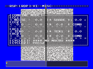
 Noise: Add a random dither pattern to surface each cycle

 When to use Add?
In an equally dark environment, such as the inside of a building, lights and surfaces under direct sunlight usually burnout to white relative to the surrounding colours. These surfaces should use Add.
When everything is equally brightly lit, the shadows become 'darker' and the scene can return to using normal texture shading.
By using Add in addition to Normal, basically gives you 512 levels of brightness and a more realistic lighting effect.
Resources:
/header/gbi.htm (contains all Combiner Multiplexor Preset Combinations)
/tutorial/graphics/4 (Tutorial explination of Combiner. Not as in depth as above)
Compile Tests
============================================================
To help work out the bit orders and lengths I compiled a series of demos with a custom Combiner.
I list each C code then I list the hex output from ROM.
Below That I print the bit map.
Corrections Listed below have now been input above but kept for reference.
Also you may notice that I assigned 5 bits to b0 and 3 to b1.
This was wrong and has also been corrected above.
Oh My... I just found that the docs actually specify Bit Lengths and Shift Values Already... They were under my nose but I couldn't see them... ah well, the compiling was still useful since there are order issues with regards to b1, A1 and C1.
Control1 All 0
#define G_CC_MYNEWMODE 0,0,0,0, 0,0,0,0
FC FF FF FF FF FF FF FF
Control2 All Combine
#define G_CC_MYNEWMODE COMBINED,COMBINED,COMBINED,COMBINED, COMBINED,COMBINED,COMBINED,COMBINED
FC 00 00 00 00 00 00 00
#define G_CC_MYNEWMODE 0,COMBINED,COMBINED,COMBINED, COMBINED,COMBINED,COMBINED,COMBINED
FC F0 00 00 00 00 00 00 1CYC
FC F0 01 E0 00 00 00 00
1111 1100 1111 00000 000 000 1111 00000
00000 000 000 000 000 000 000 000 000 000 a0 a1 Seems good
#define G_CC_MYNEWMODE COMBINED,0,COMBINED,COMBINED, COMBINED,COMBINED,COMBINED,COMBINED
FC 00 00 00 F0 00 00 00 1CYC
FC 00 00 00 FF 00 00 00
1111 1100 0000 00000 000 000 0000 00000
11111 111 000 000 000 000 000 000 000 000 b0 seems good, b1 is d0
#define G_CC_MYNEWMODE COMBINED,COMBINED,0,COMBINED, COMBINED,COMBINED,COMBINED,COMBINED
FC 0F 80 00 00 00 00 00 1CYC
FC 0F 80 1F 00 00 00 00
1111 1100 0000 11111 000 000 0000 11111
00000 000 000 000 000 000 000 000 000 000 c0 c1 seems good
#define G_CC_MYNEWMODE COMBINED,COMBINED,COMBINED,0, COMBINED,COMBINED,COMBINED,COMBINED
FC 00 00 00 00 03 80 00 1CYC
FC 00 00 00 00 03 81 C0
1111 1100 0000 00000 000 000 0000 00000
00000 000 000 000 111 000 000 111 000 000 d1 ok, d0 is b1
#define G_CC_MYNEWMODE COMBINED,COMBINED,COMBINED,COMBINED, 0,COMBINED,COMBINED,COMBINED
FC 00 70 00 00 00 00 00 1CYC
FC 00 70 00 00 E0 00 00
1111 1100 0000 00000 111 000 0000 00000
00000 000 111 000 000 000 000 000 000 000 A0 ok, A1 is B0
#define G_CC_MYNEWMODE COMBINED,COMBINED,COMBINED,COMBINED, COMBINED,0,COMBINED,COMBINED
FC 00 00 00 00 00 70 00 1CYC
FC 00 00 00 00 00 70 38
1111 1100 0000 00000 000 000 0000 00000
00000 000 000 000 000 111 000 000 111 000 B0 is A1, B1 is OK
#define G_CC_MYNEWMODE COMBINED,COMBINED,COMBINED,COMBINED, COMBINED,COMBINED,0,COMBINED
FC 00 0E 00 00 00 00 00 1CYC
FC 00 0E 00 00 1C 00 00
1111 1100 0000 00000 000 111 0000 00000
00000 000 000 111 000 000 000 000 000 000 C0 is OK, C1 is D0
#define G_CC_MYNEWMODE COMBINED,COMBINED,COMBINED,COMBINED, COMBINED,COMBINED,COMBINED,0
FC 00 00 00 00 00 0E 00 1CYC
FC 00 00 00 00 00 0E 07
1111 1100 0000 00000 000 000 0000 00000
00000 000 000 000 000 000 111 000 000 111 D0 is C1, D1 is OK
GoldenEye/Perfect Dark Colour Combiner and Render Mode Translations